Table of Contents
Designers and engineers frequently need to modify, improve, complete, and edit STL Files for 3D printing. Modern software for working with triangle meshes, or as its creators like to refer to it, the “Swiss Army Knife” for editing STL files and 3D meshes, is Autodesk’s Meshmixer.
In addition to optimizing triangle meshes, Meshmixer allows users to resculpt entire sections, stylize the model, or add useful features.
Tip #6: Adding Thickness
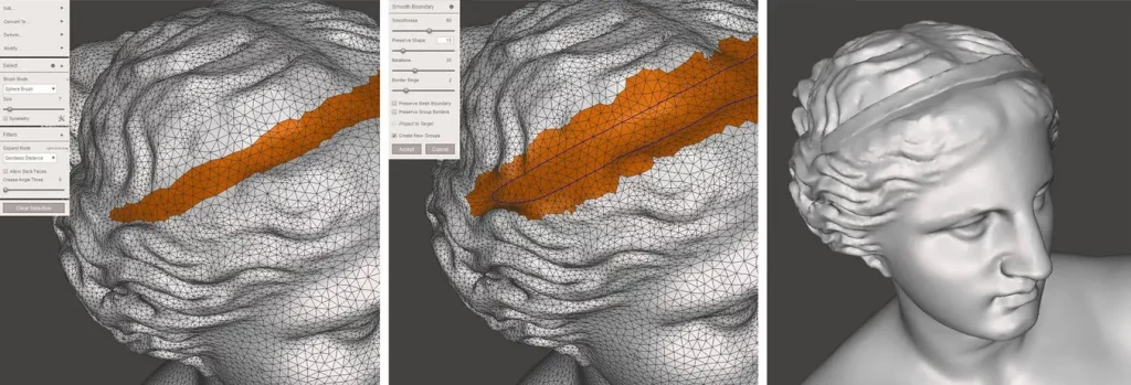
Any feature must have a minimum wall thickness or detail size, depending on the 3D printer and 3D printing technology, to be visible after 3D printing. Stereolithography 3D printers are capable of reproducing some of the finest details.
The Extrude command can be used in a specific way to give a mesh more thickness. Using Brush mode, which enables selecting (and deselecting by holding Ctrl), select the area that needs thickening. The selection can be smoothed by selecting Modify > Smooth Boundary from the popup menu. The selection will be cleaner if the Smoothness and Iterations parameters are increased. Select Edit > Extrude (D) and set the Direction to Normal.
Tip #7: Hollowing Out Parts
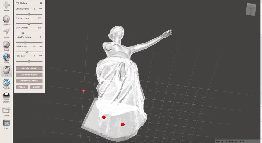
When you’re not printing functional parts that need a certain amount of strength, adding wall thickness to hollow out your design can be a great way to save a lot of material and time.
Select Edit > Hollow to add a wall thickness to the entire model. The 3D printing technology determines the minimum wall thickness. The minimum offset value for SLA and selective laser sintering (SLS) is 1 mm.
Include at least two 1.5 mm diameter holes for SLA, one as close to the build platform as possible and the other on the opposite side. This allows the resin to escape, preventing a pressure differential during the 3D printing process. It also ensures proper isopropyl alcohol (IPA) flow during cleaning and subsequent air venting.
For SLS models, drill two 2 mm holes or one 4 mm hole to allow the entrapped powder to escape. It is possible to generate holes automatically or to specify custom locations by double-clicking.
After creating holes, run Edit > Make Solid to ensure a watertight model. This is a time-consuming process, so make sure the model is now ready for 3D printing.
Using the Analysis > Stability tool, the object volume has been reduced by more than 75%, considerably reducing material usage and printing time.
Tip #8: Thickness Analysis
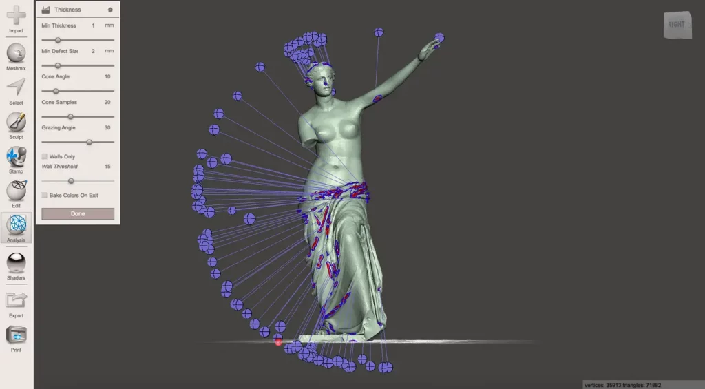
Use Analysis > Thickness to see if the model’s wall thickness is within acceptable limits for the 3D printing technology. Loss of details or, in the worst-case scenario, print failure could result from insufficient wall thickness.
The Minimum Defect Size setting specifies the smallest size required for the area to be marked below the threshold. The Minimum Thickness setting determines whether the wall thickness satisfies this dimension. Technical terms such as Cone Angle, Cone Samples, and Grazing Angle relate to the number of calculated rays from one side to the other and the angle between them to calculate wall thickness. Processing times will be faster if the cone samples are lowered and the grazing angle is raised.
Only the largest low wall thickness areas on the tunic will require modification with SLA 3D printing, for example, using the Inflate brush, according to the analysis of the single-armed Venus model.
Tip #9: Generating Supports
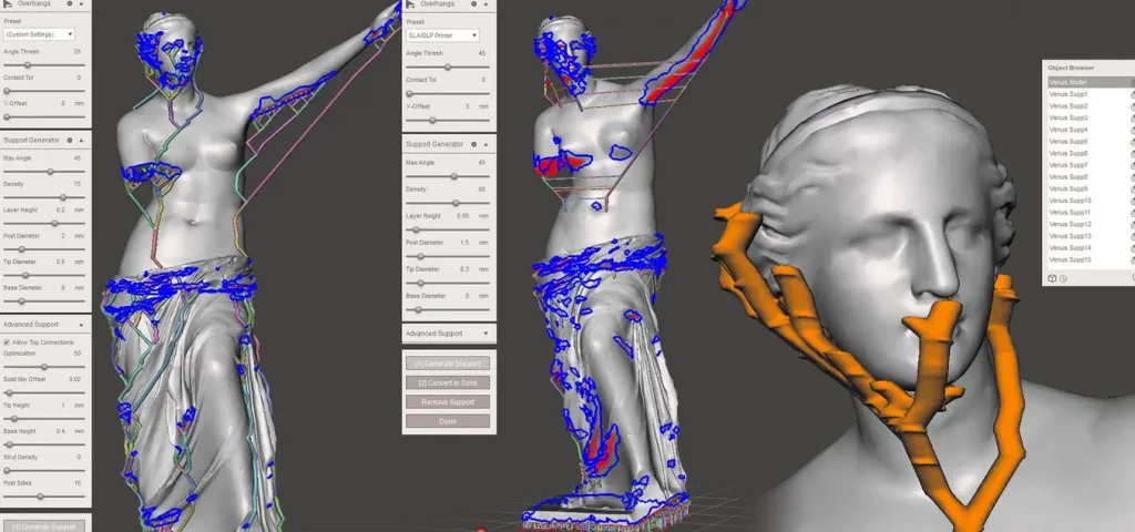
The Venus sculpture was not produced more than 2,000 years ago with 3D printing design principles in mind. Fused deposition modeling (FDM) and SLA 3D printers will need support structures for printing to succeed. Directly embedding support structures into the mesh is possible with Meshmixer. In contrast to raft-based supports, they are built using bifurcating strands that extend up to the overhang, which can save a significant amount of material.
Select Analysis > Overhangs and a 3D printer-specific preset from the main menu. Adding a Contact Tolerance specifies the distance from the support structure’s tip to the model to facilitate breakaway. Open the Support Generator now to see settings that are self-explanatory.
Check Allow Top Connections under Advanced Support for models requiring tall support structures. By doing this, supports will be made that begin somewhere on the model itself rather than at the build plate.
Hit Generate Supports after making any necessary adjustments. Because the support generator requires a lot of processing power, it can occasionally be helpful to run another Edit > Remesh or Edit > Reduce operation on large models to reduce the number of triangles. It also helps if the model is already in place, snapped to the XY plane with the Z-axis up. To remove individual supports from high-detail areas that might affect the product geometry, are prone to printing failure, or will be challenging to remove after printing, press Ctrl + LMB.
Convert to Solid joins all connected supports into a single object once all support structures have been implemented. The Edit > Separate Shells command then enables saving support structures independently from the model to use various slicer software 3D printing settings.
Tip #10: Creating Wires, Tubes, and Channels
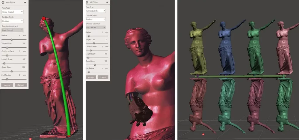
If done manually, adding wires to a 3D model can be time-consuming and difficult when connecting multiple parts in a single print. When using the potent Edit > AddTube tool, MeshMixer’s delegation of this step of the modeling process will lead to a successful model. To connect a tube with specified start and end radii, the user can specify two points on the mesh surface. With adjustable tangent strength, the Spline type allows for normal tube curvature along the start and end faces. When using AutoRoute (Smooth), you can make a tube that extends as far through the model as possible, which is useful for fluid channels and electrical wiring routes.
When Boolean is selected in Combine Mode, an external tube is added to the mesh while an internal tube is removed to produce an internal channel. Append inserts a fresh shell without merging them into the original object.
Edit > Transform (T) and Edit > Mirror can resize and position objects if you want to make a collection of miniature objects connected by a sprue-type connection. The object can be fixed to the ground plane using Edit > Align. Select the new object in the object browser after selecting Edit > Duplicate, and then use the Transform tool to move it along the X-axis. To combine the models into a single object and quickly produce linear patterns, choose the two objects, then perform the Combine operation. It’s best to use other software tools, like the Array Modifier in Blender, for more complex object patterning operations.
Bonus Tip: Stylistic Variations
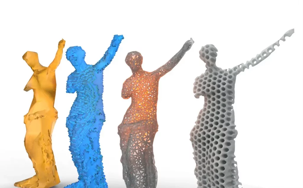
To encourage designers to use their imaginations when editing meshes, Meshmixer includes a list of stylistic alternatives.
Voxelize
The Edit > Make Solid command from the main menu creates a watertight solid from mesh surfaces by reconfiguring the object into a voxel representation. A weird voxelized model is produced if Blocky mode is selected under Solid Type and large cell size. The trick is to first rotate the object by 45 degrees over the X or Z axis using the Edit > Transform tool to avoid straight overhangs that require support structures. To make the bottom flat once more, select Edit > Plane Cut.
Low Poly
Creating good low polygonal models takes a lot of manual design work and many hours. With the help of MeshMixer, even complex objects can be transformed into eye-catching low poly pieces. You can complete this in two passes:
- Find the smallest triangle size required to maintain detail first. By eliminating extraneous information, the second pass’s experimentation is sped up. Relative Density mode can be selected by clicking Edit > Remesh. With an unchecked Preserve Sharp Edges checkbox, lower the density slider until the geometry is adequately represented.
- Press Accept once more, then select Edit > Remesh. This time, specify the length of the longest edge needed in the low poly model under Edge Length using the Target Edge Length mode. Once you’ve checked Preserve Sharp Edges, play around with the Regularity and Sharp Threshold parameters to make the model resemble a creative rendition of the original.
Find the smallest triangle size required to maintain detail first. By eliminating extraneous information, the second pass’s experimentation is sped up. Relative Density mode can be selected by clicking Edit > Remesh. With an unchecked Preserve Sharp Edges checkbox, lower the density slider until the geometry is adequately represented.
Press Accept once more, then select Edit > Remesh. This time, specify the length of the longest edge needed in the low poly model under Edge Length using the Target Edge Length mode. Once you’ve checked Preserve Sharp Edges, play around with the Regularity and Sharp Threshold parameters to make the model resemble a creative rendition of the original.
Wireframe
After applying the first Remesh pass described in the Low Poly section, an open wireframe-style model can be produced. Then select Edges for the Pattern Type under Edit > Make Pattern in the main menu. Every edge gets a wire as a result. For a pattern resembling a Voronoi diagram, select Dual Edges. For FDM 3D printing, the element dimension (ED) stands for the wire diameter, which should be at least 2 or 2.5 mm and 1 mm for SLS and SLA 3D printing, respectively. Grid Smoothing is a sophisticated option that seamlessly combines all wireframe elements, creating a more appealing mechanical and visual design.
Which Meshmixer feature do you use the most? And share your masterpieces with us in the comments below or on our Facebook page to let us know your ideas, and we would appreciate seeing pictures of your works of art! Sign up for our free weekly newsletter to receive all the latest 3D printing info in your email!


