
This tutorial will cover all the information you require about support structures. These frail, breakaway structures support your model’s cantilevered and steep overhanging portions. The Support Generation Tool makes adding, moving, and removing supports simple. The supports are built as a network of connected pieces so they can be removed from your model easily, despite appearing as individual pillars in the software.
When are supports necessary?
When models have pronounced overhangs or unsupported regions, supports are used. For instance, if you printed an arch, the center of the arch might need support material because nothing would support the top layer from below when your printer tried to print it. Because there is nothing to support the molten plastic as it is extruded out of the nozzle, if you tried to print this arch without support material, you might notice that the top layers of the arch appear to sag and droop.
As a general rule, extrusion-based printers can typically support less than 45 degrees of overhang angles. Most of the plastic layer is supported by the layer below it at these shallow angles. The edges of your layer may start to deform if you use steeper overhang angles; at that point, you might want to add support material to the part.
Let’s start by looking at a typical model that can be used to determine the kinds of overhang angles your printer can handle. What kinds of angles your printer can produce smoothly can be determined using Thingiverse’s Massive Overhang Test. The 60-70 degree sections of this part will probably not print as smoothly as you would like if you attempt to print it on your machine. This test will establish a helpful baseline for the angles your machine can support. The performance of these overhangs will depend on your layer height, temperature, material, and several other factors. Let’s use your massive overhang test print as an example. It might show that any angle greater than 45 degrees would require support material. This knowledge will be put to use in the tutorial’s following section.
How to Add Supports
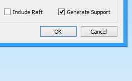
Simplify3D makes it simple to add support materials to your print when you come across a model that does. Let’s begin by importing a model we know will need assistance. The Moai statue created by alien000 will be used. This model is fairly large, so you should probably scale it down after importing it into the program to be about 25% of its original size (if you need assistance with this step, read our Importing and Manipulating Models tutorial). This model makes it evident that there are several places where our 45-degree overhang angle limit will likely be broken. To print the Moai model, add a new FFF process or alter an existing one. Open the FFF process settings and turn on the Generate Support Material option to add support material for this model. The software has already added the necessary support structures for the nose, chin, eyebrows, and ears if you select Prepare to Print!
How to Modify Where Support Material is Placed
The software makes this process very simple and gives you more choices if you want more control over where the support materials are placed. What would happen, for instance, if you decided against printing support material inside the Moai statue’s nose? The nose may have printed successfully without the support material the first time you printed this model. Less cleanup would be required at the end of the print if the support material could be removed from this area. We must first go back to the model view before we can proceed. Make sure to close the preview if you were previously viewing a line-by-line G-Code preview to see the Moai statue’s unprocessed digital model. Go to Tools > Customize Support Structures or click the very last icon in the toolbar on the right side of the screen to display the support generation toolbar.
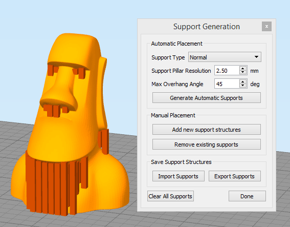
There are several sections in the support generation toolbar. The software can recommend where it thinks support material is needed by using the automatic support generation options in the top section. Giving you a starting point for any future modifications can save you time. Additionally, you can switch the support type from Normal to From Build Platform Only, which will only generate supports directly touching the build plate. This option is helpful if the generated supports are challenging to remove or become trapped inside the part. Press the Generate Automatic Supports button after choosing an option. A preview of the suggested support structures will be generated based on the overhang angle you enter. In this preview, a row of vertical pillars denotes the locations where support structures are required. The pillar shape should be understood as merely a preview. The back-and-forth webbing pattern you saw earlier in the G-Code preview will continue to be used in the final print. The support pillar resolution, which controls the size of each support pillar, is the only other option in this section. You might want to use a smaller value, such as 1-2mm if your model is highly intricate and has many small features. In this instance, the features are all significant and extensive, so a resolution of 4-6mm should be adequate. The pillars are also simpler to interact with at a higher resolution.
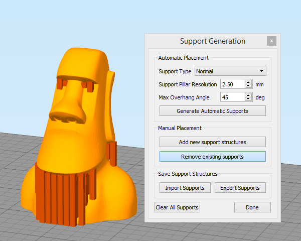
A few options in the following section of the support generation toolbar allow us to add or remove existing support material locations manually. These tools can be combined to produce the ideal support material layout for our model. We previously mentioned the possibility of removing the support structure from the Moai statue’s nose. To accomplish this, click the “Remove existing supports” button, then left-click the support pillars you want to remove from the screen. To leave this mode once you have finished removing these pillars, click the “Remove existing supports” button. The procedure is very similar if you want to add support material in new areas of the model. In this situation, you would click the “Add new support structures” button before selecting the locations where the new support pillars should be placed. When you’re done, click the button a second time to end that editing mode.
Saving Your Factory File
You might want to save your work after making several adjustments to the support structures of your model so that you can reload it later. Simply saving a “factory file” for your current workspace is the best way to accomplish this. Your imported STL file, defined FFF processes, support structures you’ve built, and even the orientation and placement of the models on your build table surface are all included in the factory file. You can share your file with a friend who uses a similar computer or use it as a great way to save all of your work so that you can continue where you left off. Select File > Save Factory File to save a factory file. The support generation toolbar offers the option to save the support structures separately, but doing so is typically not advised because it will remove the relative location of the original STL file.
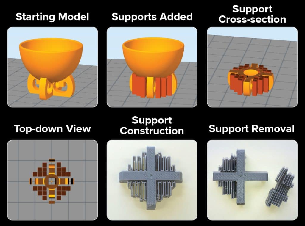
Your supports look like individual pillars when you view them on your monitor, but they will form a network when they are built. These networks of support are simple to eliminate on your end! Supports can be added, previewed, constructed, and removed in the image on the left.
Advanced Support Settings
Additional FFF settings are available to regulate how the support structures will be printed. Click Show Advanced in the bottom left of your FFF settings to see these options. This will open up several extra tabs containing many sophisticated settings to create your prints.
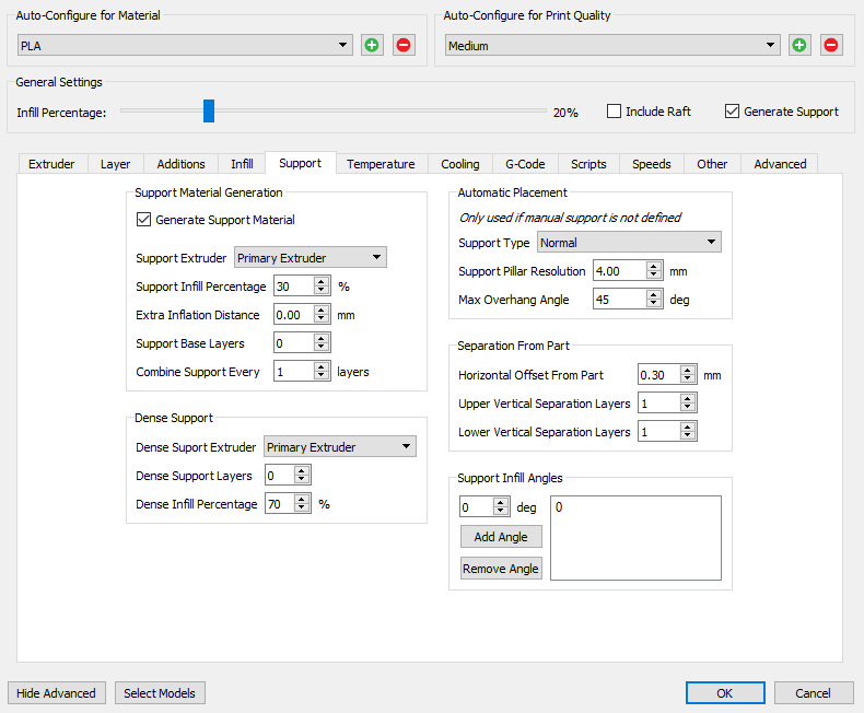
Select the Support tab to view the various settings that affect how your support material is printed. You’ll see that the options in the Automatic Placement section match those in the support generation toolbar exactly. You can set these parameters appropriately and let the software generate the support structures automatically if you do not need to manually edit them for your model, eliminating the need to open the Customize Support Structures window previously.
The Separation from the Part section finds all settings that control how easily the support material will separate from your final solid part. How much space there is between the support structures and the part’s outline will depend on the horizontal offset. Increase this setting to create a larger space between the support and the part if you are having trouble removing your support material. Typically, a value of 0.2 to 0.4 mm suffices. Once the desired values have been entered, click Save so that the new settings will be used for the subsequent model preparation.
Congratulations! All the information required to add and change support structures in the Simplify3D software has now been covered. The ability to alter the placement of these break-away structures can significantly improve the quality of your prints and significantly reduce the post-processing time required.

